1. Introduction
In the Automobile industry an electronic control unit (ECU) is a embedded electronic device, basically a digital computer, that read signals coming from sensors placed at various parts and in different components of the car and depending on this information controls various important units e.g. engine and automated operations within the car and also keeps a check on the performance of some key components used in the car.

An ECU is basically made up of hardware and software (firmware). The hardware is basically made up of various electronic components on a PCB. The most important of these components is a microcontroller chip along with an EPROM or a Flash memory chip. The software (firmware) is a set of lower-level codes that runs in the microcontroller.
MovEnergy uses a standard ECU with sensors turbo speed, temperature of the air , turbo, voltage,fuel which regulates arrived dropwise fuel oil and water to maintain the speed of rototion of generator has + – 25,000 rpm. She has completely reprogram the ECU.
The ECU is characterized by:
· many analog and digital I/O lines (low and high power)
· power device interface/control
· different communication protocols (CAN, KWP-2000, etc.).
· large switching matrices for both low and high power signals
· high voltage tests
· intelligent communication interface adapters (standard or custom)
· automatic fixture recognition and software sequence enable
· power device simulation
2. Different Types of ECU’s
Depending on what it is used for ECU’s are named and differentiated as below :
ECM – Engine Control Module. (Many a times in the industry ECM are called as ECU – Engine Control Unit).
The ECM also known as EMS (Engine management system) is an ECU in an internal combustion engine that controls various engine functions like fuel injection, ignition timing and idle speed control system. All these control are done based on data (like engine coolant temperature, air flow, crank position etc) received from various sensors.
The ECM’s also learns about the engine as we drive our car. The “learning” is actually a process that the ECU uses to track the tolerance changes of the sensors and actuators on the engine. For examples the idle-air bypass valve (automatic choke) at idle with the A/C in the CAR on and off. The ECM stores these “learned” values in battery backed-up RAM so that it doesn’t have to start from scratch the next time the engine is turned over. A detail discussions on ECM’s are done in the later part of the paper.
With the enforcement of the Federal Emission Regulations in 1981 ECU’s are being used popularly in most of the vehicles. In the aeronautical applications these systems are popularly called as ‘FADECs’ (Full Authority Digital Engine Control).
3. Typical Inputs/Outputs of an ECU
An ECU consists of a number of functional blocks:
1. Power Supply – digital and analog (power for analog sensors)
2. MPU – microprocessor and memory (usually Flash and RAM)
3. Communications Link – (e.g. CAN bus)
4. Discrete Inputs – On/Off Switch type inputs
5. Frequency Inputs – encoder type signals (e.g. crank or vehicle speed)
6. Analog Inputs – feedback signals from sensors
7. Switch Outputs – On/Off Switch type outputs
8. PWM Outputs – variable frequency and duty cycle (e.g. injector or ignition)
9. Frequency Outputs – constant duty cycle (e.g. stepper motor – idle speed control)
And typically in an Engine Control Unit there are many kinds of sensors and actuators connected and its very important to know the kind of I/O they require.
Let us have a look at some of the most typical kind of sensors and actuators that are connected to an Engine control module and what kind of I/O’s do they require.
Temperature of the exhaust gas (EGT)
This instrument measures the temperature of the exhaust gases as they escape from the combustion chamber and pass into the exhaust manifold. It provides an overview of combustion temperatures and to monitor the quality of the air / fuel mixture. Too high temperature indicates a lean mixture, while a low temperature indicates a rich mixture.
Turbine Inlet Temperature (TIT)
TIT is the highest temperature inside a gas turbine engine and is one of the limiting factors of the amount of power the engine can produce. TIT is difficult to measure, but exhaust gas temperature, or EGT, which is the temperature of the gas as it leaves the turbine, relates to TIT and is normally the parameter measured.

Turbine speed sensor (TSS)
Magnetic pickups (MPUs) are speed sensors that detect the speed of a prime mover, typically an engine or turbine. The MPU is installed next to a drive shaft gear made of a material that reacts to a magnetic field. As each gear tooth passes the MPU, the gear interrupts the MPU’s magnetic field, and an alternating voltage is developed. The frequency of this voltage is translated by the speed control into a signal that accurately depicts the speed of the prime mover.
The exhaust gas oxygen sensor (EGO), or lambda sensor
Lambda sensors produce a voltage signal that recognises the amount of unburnt oxygen in the exhaust. An oxygen sensor is essentially a battery that generates its own voltage. When hot (at least 250 °C), the zirconium dioxide element in the sensor’s tip produces a voltage that varies according to the amount of oxygen in the exhaust compared to the ambient oxygen level in the outside air. The greater the difference, the higher the sensor’s output voltage.
5. Design and Testing
The traditional way to develop automotive embedded systems has been to build hardware boards that represent all or part of each ECU and part of its surroundings, often called plant models, and use them for bench testing. Unfortunately, the bench approach has many limitations.
First, creating all the needed hardware boards is costly.
Second, the performance requirements of the most powerful ECU’s (those used for Powertrain control) are so demanding that it is no longer possible to build boards that allow adequate measurements to be taken.
Finally, and most importantly, this bench testing approach is based on a sequential design process where hardware is developed, plant model prototypes are built and software development begins.
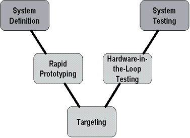
To overcome these limitations control design engineers have adopted a highly efficient design process often referred to as the “V” diagram. Though originally developed to encapsulate the design process of software applications, many different versions of this diagram can be found to describe different product design cycles. The one given below is typically what is used in ECU design cycle.

In this diagram the general progression of time in the development stages is shown from left to right. However, this is often an iterative process, and the actual development will not proceed linearly through these steps. Instead, you will spend time in each step and even have to backtrack from time to time. The goal is to make this cycle as efficient as possible by minimizing the amount of backtracking between steps as well as the time spent in each step.
The y-axis of this diagram can be thought of as the level at which the system components are considered. Early on in the development, the requirements of the overall system must be considered. As the system is divided into sub-systems and components, the process becomes very low-level down to the point of loading code onto individual processors.
Afterwards, components are integrated and tested together until such time that the entire system can enter final production testing. Therefore the top of the diagram represents the high-level system view and the bottom of the diagram represents a very low-level view.
Lets have a look into these steps one-by-one.
System Definition.
In this step initially the design engineers documents the needs and requirements of the project using spreadsheet or word processing applications. The documentation also takes care about the various specification of the engine and the various norms it needs to comply with. It also marks the limit levels of the parameters involved in controlling the engine.
Once the specifications are documented the actual design process begins in which first a software model of the ECU and the engine is built.
And once the models are build the third step involves software-in-the-loop simulation. In this step both the software models; ECU model and Engine model; are connected together in a closed feedback loop and then simulated to analyze the dynamic characteristics of the entire system. During the simulation the ECU model monitors the output from the Engine model and adjusts the inputs to the Engine model in order to improve the performance of various engine functions like fuel injection, ignition etc.

Hardware-in-the-loop Simulation (HIL)
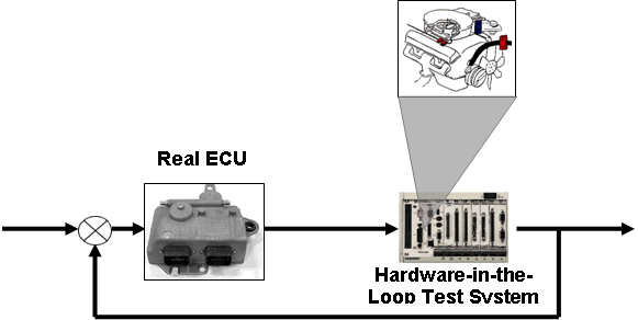
Once the code containing the control algorithm is downloaded to the ECU we can test the performance of the ECU under extreme conditions, which cannot be achieved in real world, by performing HIL simulation. In this step the actual ECU is tested by simulating an engine using the Engine model that we had created earlier.
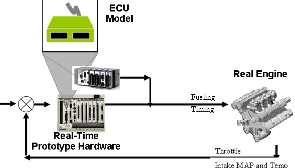
In vice-versa to what we did in RCP, here in HIL the software model of the Engine is downloaded to a Real-Time hardware and the appropriate I/O interfaces are provided. These I/O are then connected to the actual ECU. Then various engine conditions can be simulated and the ECU can be tested to its limits which wouldn’t be possible if it was tested using an actual Engine.
.

Again like RCP the hardware for the HIL is decided according to the signals and the sensors that we are going to simulate, this can be chosen from the list given in the Input/Output section


