
Turbochargers, best known for making cars go faster, are taking a lead in the race to cut carbon dioxide (CO2) emissions.
Automotive manufacturers are being challenged to meet increasingly stringent emissions and fuel efficiency requirements – industry experts agree that turbo technology offers one of the most cost-effective routes to achieving the desired results.
The basic concept of a turbocharger is to recycle wasted energy from exhaust gas, transforming more of the fuel energy consumed into power. A turbocharged engine, therefore offers improved fuel economy, less CO2 emissions and better performance over a non-turbocharged engine.
Turbocharging allows auto manufacturers to reduce their engine sizes and therefore emissions while continuing to deliver the power and performance customers demand. “Turbochargers offer the fastest response to global warming at a lower cost per vehicle than any other technology”, Alex Ismail, Chief Executive of Honeywell Transportation explains to BBC News.
 Turbochargers are no longer only for boy racers,” insists Ulrich Hackenberg, Volkswagen Group board member in charge of research and development. Turbochargers push compressed air into the cylinders of an engine, thus allowing more fuel to be added to produce more power.
“It offers a new way of downsizing,” Mr Hackenberg says, pointing to how turbo helps carmakers switch to smaller, less thirsty engines with lower emissions that nevertheless deliver “more power, more torque and more driving fun”.
Ian Robertson, BMW Group board member in charge of sales and marketing, agrees.
“More often than not, we’re increasing both the power and the acceleration capabilities, while at the same time we improve fuel economy and reduce CO2 emissions,” he says.
“Turbo is playing a big part in it.”
TURBOCHARGER BASICS
The turbocharger’s basic functions have not fundamentally changed since the times of Alfred Büchi. A turbocharger consists of a compressor and a turbine connected by a common shaft. The exhaust-gas-driven turbine supplies the drive energy for the compressor.
Compressor

Design and function
Turbocharger compressors are generally centrifugal compressors consisting of three essential components: compressor wheel, diffuser, and housing. With the rotational speed of the wheel, air is drawn in axially, accelerated to high velocity and then expelled in a radial direction.
The diffuser slows down the high-velocity air, largely without losses, so that both pressure and temperature rise. The diffuser is formed by the compressor backplate and a part of the volute housing, which in its turn collects the air and slows it down further before it reaches the compressor exit.
Operating characteristics
The compressor operating behaviour is generally defined by maps showing the relationship between pressure ratio and volume or mass flow rate. The useable section of the map relating to centrifugal compressors is limited by the surge and choke lines and the maximum permissible compressor speed.
Surge line
The map width is limited on the left by the surge line. This is basically “stalling” of the air flow at the compressor inlet. With too small a volume flow and too high a pressure ratio, the flow can no longer adhere to the suction side of the blades, with the result that the discharge process is interrupted. The air flow through the compressor is reversed until a stable pressure ratio with positive volume flow rate is reached, the pressure builds up again and the cycle repeats. This flow instability continues at a fixed frequency and the resultant noise is known as “surging”.
 Compressor map of a turbocharger for passenger car applications
Choke line
The maximum centrifugal compressor volume flow rate is normally limited by the cross-section at the compressor inlet. When the flow at the wheel inlet reaches sonic velocity, no further flow rate increase is possible. The choke line can be recognised by the steeply descending speed lines at the right on the compressor map.
Turbine
The turbocharger’s basic functions have not fundamentally changed since the times of Alfred Büchi. A turbocharger consists of a compressor and a turbine connected by a common shaft. The exhaust-gas-driven turbine supplies the drive energy for the compressor.
Design and function
The turbocharger turbine, which consists of a turbine wheel and a turbine housing, converts the engine exhaust gas into mechanical energy to drive the compressor. The gas, which is restricted by the turbine’s flow cross-sectional area, results in a pressure and temperature drop between the inlet and outlet. This pressure drop is converted by the turbine into kinetic energy to drive the turbine wheel.
There are two main turbine types: axial and radial flow. In the axial-flow type, flow through the wheel is only in the axial direction. In radial-flow turbines, gas inflow is centripetal, i.e. in a radial direction from the outside in, and gas outflow in an axial direction.
Up to a wheel diameter of about 160 mm, only radial-flow turbines are used. This corresponds to an engine power of approximately 1000 kW per turbocharger. From 300 mm onwards, only axial-flow turbines are used. Between these two values, both variants are possible.
As the radial-flow turbine is the most popular type for automotive applications, the following description is limited to the design and function of this turbine type. In the volute of such radial or centripetal turbines, exhaust gas pressure is converted into kinetic energy and the exhaust gas at the wheel circumference is directed at constant velocity to the turbine wheel. Energy transfer from kinetic energy into shaft power takes place in the turbine wheel, which is designed so that nearly all the kinetic energy is converted by the time the gas reaches the wheel outlet.
Operating characteristics
The turbine performance increases as the pressure drop between the inlet and outlet increases, i.e. when more exhaust gas is dammed upstream of the turbine as a result of a higher engine speed, or in the case of an exhaust gas temperature rise due to higher exhaust gas energy.
 Turbocharger turbine map
The turbine’s characteristic behaviour is determined by the specific flow cross-section, the throat cross-section, in the transition area of the inlet channel to the volute. By reducing this throat cross-section, more exhaust gas is dammed upstream of the turbine and the turbine performance increases as a result of the higher pressure ratio. A smaller flow cross-section therefore results in higher boost pressures.
The turbine’s flow cross-sectional area can be easily varied by changing the turbine housing.
Besides the turbine housing flow cross-sectional area, the exit area at the wheel inlet also influences the turbine’s mass flow capacity. The machining of a turbine wheel cast contour allows the cross-sectional area and, therefore, the boost pressure, to be adjusted. A contour enlargement results in a larger flow cross-sectional area of the turbine.
Turbines with variable turbine geometry change the flow cross-section between volute channel and wheel inlet. The exit area to the turbine wheel is changed by variable guide vanes or a variable sliding ring covering a part of the cross-section.
In practice, the operating characteristics of exhaust gas turbocharger turbines are described by maps showing the flow parameters plotted against the turbine pressure ratio. The turbine map shows the mass flow curves and the turbine efficiency for various speeds. To simplify the map, the mass flow curves, as well as the efficiency, can be shown by a mean curve
For a high overall turbocharger efficiency, the co-ordination of compressor and turbine wheel diameters is of vital importance. The position of the operating point on the compressor map determines the turbocharger speed. The turbine wheel diameter has to be such that the turbine efficiency is maximised in this operating range.
Twin-entry turbines
The turbine is rarely subjected to constant exhaust pressure. In pulse turbocharged commercial diesel engines, twin-entry turbines allow exhaust gas pulsations to be optimised, because a higher turbine pressure ratio is reached in a shorter time. Thus, through the increasing pressure ratio, the efficiency rises, improving the all-important time interval when a high, more efficient mass flow is passing through the turbine. As a result of this improved exhaust gas energy utilisation, the engine’s boost pressure characteristics and, hence, torque behaviour is improved, particularly at low engine speeds.

Turbocharger with twin-entry turbine
To prevent the various cylinders from interfering with each other during the charge exchange cycles, three cylinders are connected into one exhaust gas manifold. Twin-entry turbines then allow the exhaust gas flow to be fed separately through the turbine.
Water-cooled turbine housings

Turbocharger with water-cooled turbine housing for marine applications
Safety aspects also have to be taken into account in turbocharger design. In ship engine rooms, for instance, hot surfaces have to be avoided because of fire risks. Therefore, water-cooled turbocharger turbine housings or housings coated with insulating material are used for marine applications.
Control System
The turbocharger’s basic functions have not fundamentally changed since the times of Alfred Büchi. A turbocharger consists of a compressor and a turbine connected by a common shaft. The exhaust-gas-driven turbine supplies the drive energy for the compressor.
Target and function
The driveability of passenger car turbo engines must meet the same high requirements as naturally aspirated engines of the same power output. That means, full boost pressure must be available at low engine speeds. This can only be achieved with a boost pressure control system on the turbine side.
Control by turbine-side bypass
Today, electronic boost pressure control systems are increasingly used in modern passenger car diesel and petrol engines. When compared with purely pneumatic control, which can only function as a full-load pressure limiter, a flexible boost pressure control allows an optimal part-load boost pressure setting. This operates in accordance with various parameters such as charge air temperature, degree of timing advance and fuel quality. The operation of the flap corresponds to that of the previously described actuator. The actuator diaphragm is subjected to a modulated control pressure instead of full boost pressure.

Boost pressure control of a turbocharged petrol engine by proportional control pressure
This control pressure is lower than the boost pressure and generated by a proportional valve. This ensures that the diaphragm is subjected to the boost pressure and the pressure at the compressor inlet in varying proportions. The proportional valve is controlled by the engine electronics. For diesel engines, a vacuum-regulated actuator is used for electronic boost pressure control.
Variable turbine geometry
The variable turbine geometry allows the turbine flow cross-section to be varied in accordance with the engine operating point. This allows the entire exhaust gas energy to be utilised and the turbine flow cross-section to be set optimally for each operating point. As a result, the efficiency of the turbocharger and hence that of the engine is higher than that achieved with the bypass control.

Turbocharger for truck applications with variable turbine geometry (VTG)
Flow cross-section control through variable guide vanes: VTG
Variable guide vanes between the volute housing and the turbine wheel have an effect on the pressure build-up behaviour and, therefore, on the turbine power output. At low engine speeds, the flow cross-section is reduced by closing the guide vanes. The boost pressure and hence the engine torque rise as a result of the higher pressure drop between turbine inlet and outlet. At high engine speeds, the guide vanes gradually open. The required boost pressure is achieved at a low turbine pressure ratio and the engine’s fuel consumption reduced. During vehicle acceleration from low speeds the guide vanes close to gain maximum energy of the exhaust gas. With increasing speed, the vanes open and adapt to the corresponding operating point.
Today, the exhaust gas temperature of modern high-output diesel engines amounts to up to 830 °C. The precise and reliable guide vane movement in the hot exhaust gas flow puts high demands on materials and requires tolerances within the turbine to be exactly defined. Irrespective of the turbocharger frame size, the guide vanes need a minmum clearance to ensure reliable operation over the whole vehicle lifetime.
Bearing Systems
The turbocharger’s basic functions have not fundamentally changed since the times of Alfred Büchi. A turbocharger consists of a compressor and a turbine connected by a common shaft. The exhaust-gas-driven turbine supplies the drive energy for the compressor.
The turbocharger shaft and turbine wheel assembly rotates at speeds up to 300,000 rpm. Turbocharger life should correspond to that of the engine, which could be 1,000,000 km for a commercial vehicle. Only sleeve bearings specially designed for turbochargers can meet these high requirements at a reasonable cost.

Turbocharger bearing system (cut-away model)
Radial bearing system
With a sleeve bearing, the shaft turns without friction on an oil film in the sleeve bearing bushing. For the turbocharger, the oil supply comes from the engine oil circuit. The bearing system is designed such that brass floating bushings, rotating at about half shaft speed, are situated between the stationary centre housing and the rotating shaft. This allows these high speed bearings to be adapted such that there is no metal contact between shaft and bearings at any of the operating points. Besides the lubricating function, the oil film in the bearing clearances also has a damping function, which contributes to the stability of the shaft and turbine wheel assembly. The hydrodynamic load-carrying capacity and the bearing damping characteristics are optimised by the clearances. The lubricating oil thickness for the inner clearances is therefore selected with respect to the bearing strength, whereas the outer clearances are designed with regard to the bearing damping. The bearing clearances are only a few hundredths of a millimetre.
The one-piece bearing system is a special form of a sleeve bearing system. The shaft turns within a stationary bushing, which is oil scavenged from the outside. The outer bearing clearance can be designed specifically for the bearing damping, as no rotation takes place.
Axial-thrust bearing system
Neither the fully floating bushing bearings nor the single-piece fixed floating bushing bearing system support forces in axial direction. As the gas forces acting on the compressor and turbine wheels in axial direction are of differing strengths, the shaft and turbine wheel assembly is displaced in an axial direction. The axial bearing, a sliding surface bearing with tapered lands, absorbs these forces. Two small discs fixed on the shaft serve as contact surfaces. The axial bearing is fixed in the centre housing. An oil-deflecting plate prevents the oil from entering the shaft sealing area.
Oil drain
The lubricating oil flows into the turbocharger at a pressure of approximately 4 bar. As the oil drains off at low pressure, the oil drain pipe diameter must be much larger than the oil inlet pipe. The oil flow through the bearing should, whenever possible, be vertical from top to bottom. The oil drain pipe should be returned into the crankcase above the engine oil level. Any obstruction in the oil drain pipe will result in back pressure in the bearing system. The oil then passes through the sealing rings into the compressor and the turbine.
Sealing
The centre housing must be sealed against the hot turbine exhaust gas and against oil loss from the centre housing. A piston ring is installed in a groove on the rotor shaft on both the turbine and compressor side. These rings do not rotate, but are firmly clamped in the centre housing. This contactless type of sealing, a form of labyrinth seal, makes oil leakage more difficult due to multiple flow reversals, and ensures that only small quantities of exhaust gas escape into the crankcase.
Water-cooling

Turbocharger for passenger car gasoline applications with water-cooled bearing housing
Petrol engines, where the exhaust gas temperatures are 200 to 300 °C higher than in diesel engines, are generally equipped with water-cooled centre housings. During operation of the engine, the centre housing is integrated into the cooling circuit of the engine. After the engine’s shutdown, the residual heat is carried away by means of a small cooling circuit, which is driven by a thermostatically controlled electric water pump.
Development
As turbochargers have to meet different requirements with regard to map height, map width, efficiency characteristics, moment of inertia of the rotor and conditions of use, new compressor and turbine types are continually being developed for various engine applications. Furthermore, different regional legal emission regulations lead to different technical solutions.
The compressor and turbine wheels have the greatest influence on the turbocharger’s operational characteristics. These wheels are designed by means of computer programs which allow a three-dimensional calculation of the air and exhaust gas flows. The wheel strength is simultaneously optimised by means of the finite-element method (FEM), and durability calculated on the basis of realistic driving cycles.
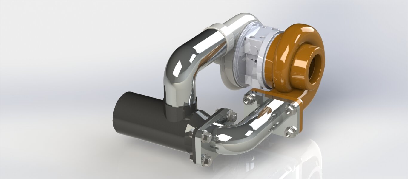
 CAD-assembled model of a turbocharger
Despite today’s advanced computer technology and detailed calculation programs, it is testing which finally decides on the quality of the new aerodynamic components. The fine adjustment and checking of results is therefore carried out on turbocharger test